 |
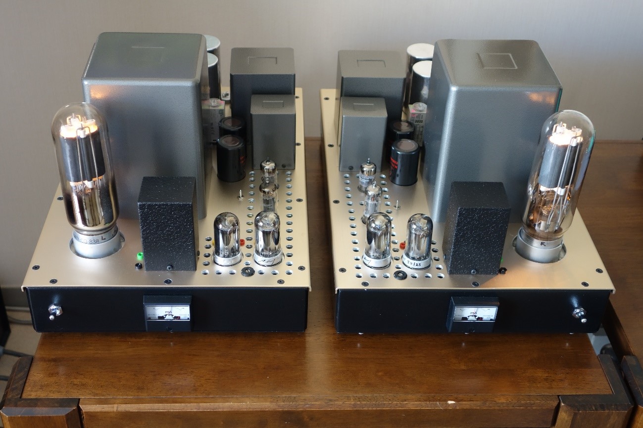
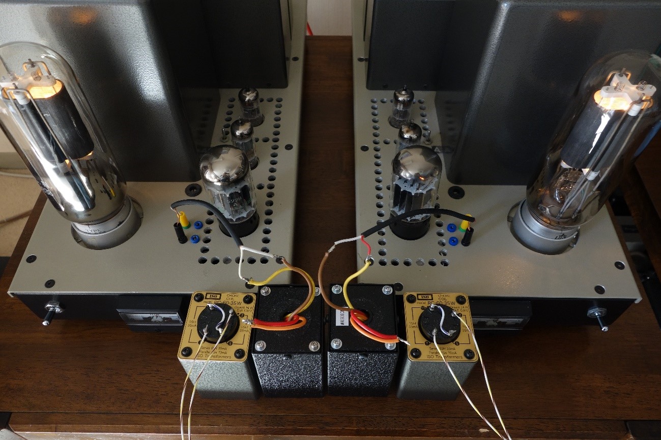
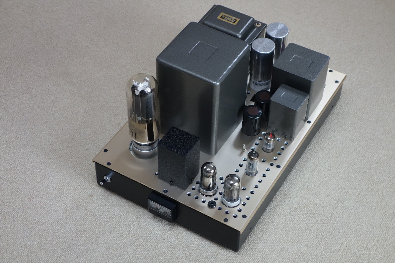
4P1Lx2, Cathode choke drive, 838 Single-ended amplifier (30W)
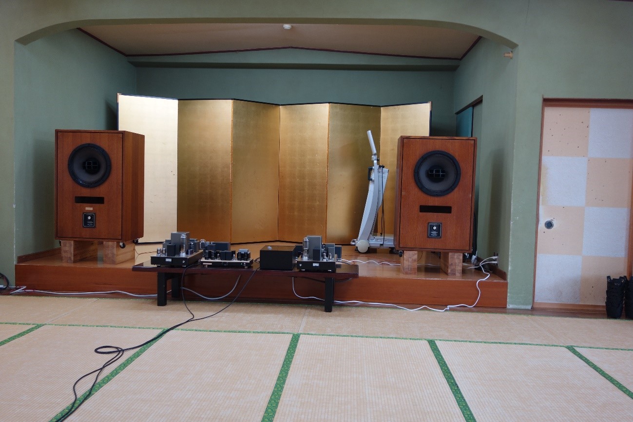
Exterior view of two units
|
Introduction
I dismounted the regulator tube drive 838 SE amp (CF+CCS by 5998A) that I used for 14 years, and This time I built a 4P1Lx2 cathode choke drive 838 SE amp (30W) on a scratch base.
The motivation is that I like the clean circuit configuration of the 4P1L cathode choke drive 811A SE amp" that I created in 2013.
In particular, the ability to use the 4P1L's unique filament midpoint tap as a cathode follower output.
The simple ripple suppression and voltage regulation circuit with the 2SD1666 provides a sufficient filtering effect, eliminating the need for a hum balancer.
The middle tap of the 4P1L filament can be directly connected to the cathode choke (the other end is ground) and the 838 glid, with lowest impedance.
I also really like the sound quality of the 4P1Lx3 parallel single- ended stereo amplifier (8W)
with enhanced power supply and decoupling circuit (built in 2015).
Therefore,I built a cathode choke drive 838 SE amp (30W),which is the combination of the above two amplifiers, as a summary of my design work.
This 4P1Lx2 parallel,cathode choke drive 838 SE amp combines the transparency and clarity of the mid-high range characteristic of the 4P1L with high output power.
I am satisfied that I was able to realize my goal.
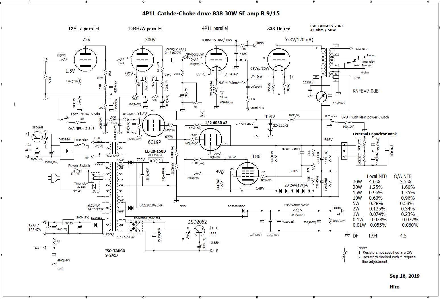
Schematic of 4P1Lx2, cathode choke drive, 838 Single-ended amplifier(30W)
(Click image to enlarge.)
Process to completion and Circuit descriptions
1. Hi-ā╩ plus bias transmitting tubes and cathode choke drive circuits are an extremely compatible combination if certain conditions are met.The DC resistance of the cathode choke allows a stable +bias voltage to be applied to the output tube, and only a + power supply is required to excite the +-region.
2. Among these tubes, the 838, with ā╩ of 50, and a bias voltage of +25 to 30V, and a grid current of 12 to 25mA, is an easy-to-use output tube suitable for cathode choke drive circuits. The sound quality of the 838, which I have become accustomed to listening, is in the middle of 100TH (more toward the lower midrange) and 811A (more toward the high range).
3. The 838 has a relatively low plate voltage (600 to 650V), and high output can be efficiently obtained by A2. (DC input: output=40% or more)
4. By applying cathode NFB to the output stage, the distortion of the output tube can be lowered, and at the same time, the low dumping factor value, which is the week point of Hi-ā╩ tubes , can be raised to the practical range. (In this case, the KNF amount is 7.2dB due to the 36āČ KNF winding, and the DF value increased from 0.35 to 1.8)
5. Local NFB is applied from the 4P1L filament midpoint tap to the first stage tube
cathode to further reduce the drive impedance. (Local NFB: -5.5dB)
6. The first experiment began in October 2017 by test listening to the 838 SE amp (CF+CCS by 5998A) output stage and the drive stage of the 811A SE amp (4P1L cathode choke drive) connected directly.
7. As it is, only about +18V bias voltage can be obtained, which is not enough for 838, so a fixed 2kāČ resistor is inserted between the cathode choke and ground, and the output power of 30W was obtained. (Distortion: 4.4%)
8. The above series resistors have a trade-off relationship in that increasing the resistance increases the + bias voltage of the output tube 838 and increases the plate current of the output tube. However, it also deepens the bias voltage of the drive tube 4P1L, which decreases the plate current of 4P1L.
9. Listening results showed that the dynamic range seemed to decrease when a series resistor was inserted.
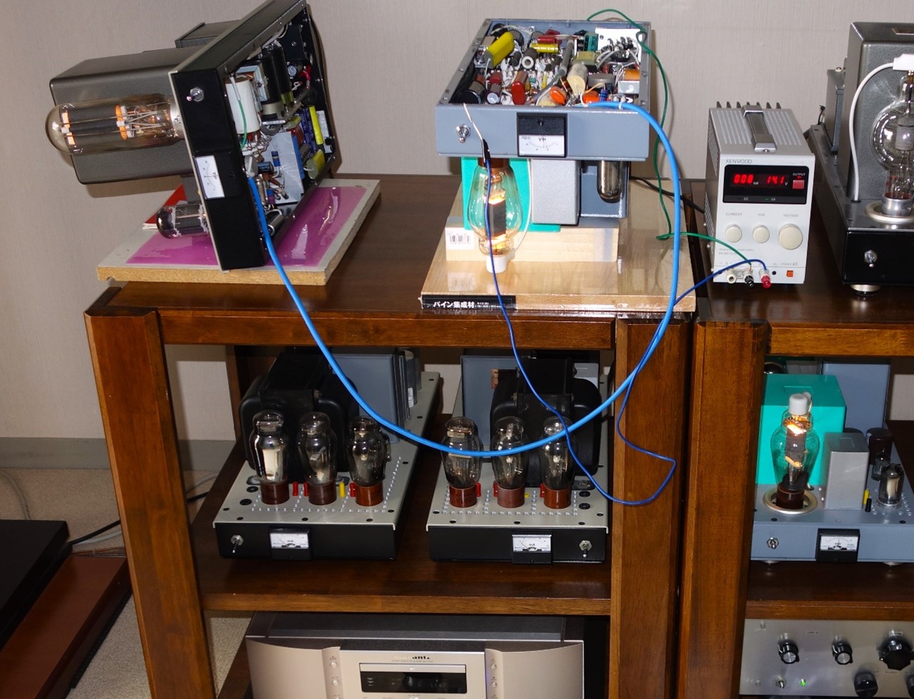
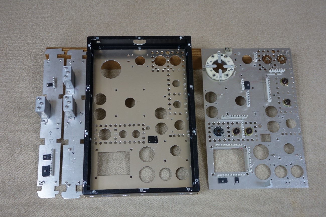
10. After the above basic experiments, a dedicated driver chassis (stereo) including voltage amplification stage and power supply section was prepared to explore a full-scale drive circuit. This facilitated circuit modification and listening experiments.
838,811A Experimental pattern, driver chassis, and Cathode choke comparison
 |
 |
 |
 |
 |
 |
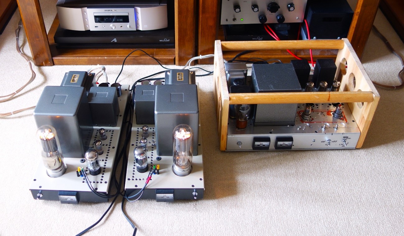
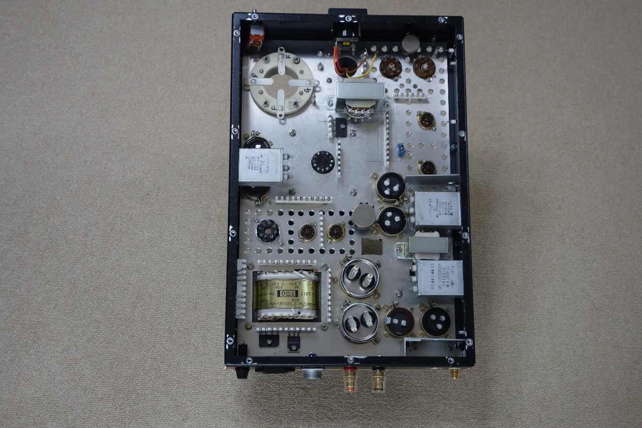
All major components, such as the power transformer, output transformer, and chokes, were disassembled and reused from a previous regulator tube drive 838 SE amp. A Noguchi transformer FMC6060HW (60H/60mA, DCR 730āČ) with a Finemet core was used as the cathode choke. The chassis was changed from Takachi SRDSL-15 to SRDSL-20 (W:450mm, H:68.2mm, D:305mm) to allow more room for component placement and heat dissipation, and to eliminated the cooling fan. On the underside of the top panel, a 2.5mm-thick aluminum plate is overlapped for a total thickness of 4.5mm, which increases the rigidity of the chassis. Additionally, it was designed so that the heads of screws will not stick out of the top panel. All high-voltage electrolytic capacitors are placed on the chassis for thermal protection.
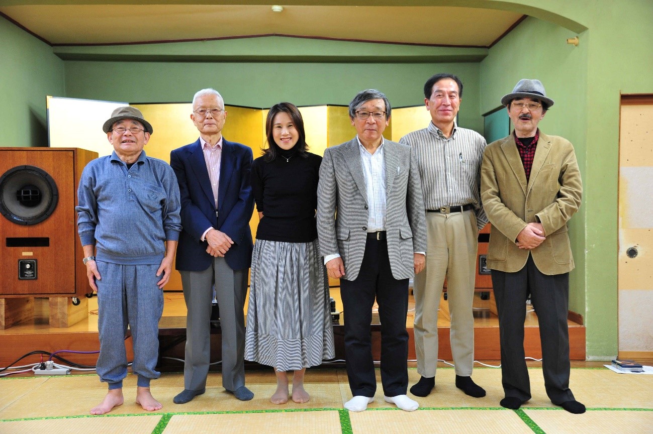
23. Sound quality evaluation and others:The 4P1Lx2, cathode choke drive, 838 SE amp (35W) were assembled one day before the 18th Audio Music Club Nagoya Exhibit (June 23, 2019) Later, after noticing the unstable performance of the output stage constant voltage power supply, the circuit was modified with reference to Morgan Jones` Valve Amplifiers-Third Edition, and output power was reduced to 30W. I presented my work at the 36th Toyama Craft Audio Club Listening Session (October 26, 2019). The event was attended by about 50 people. I received the following comments and evaluations from 12 people. .
Toyama Craft Listening Event Venue and Exhibitors
 |
 |