|
|
|
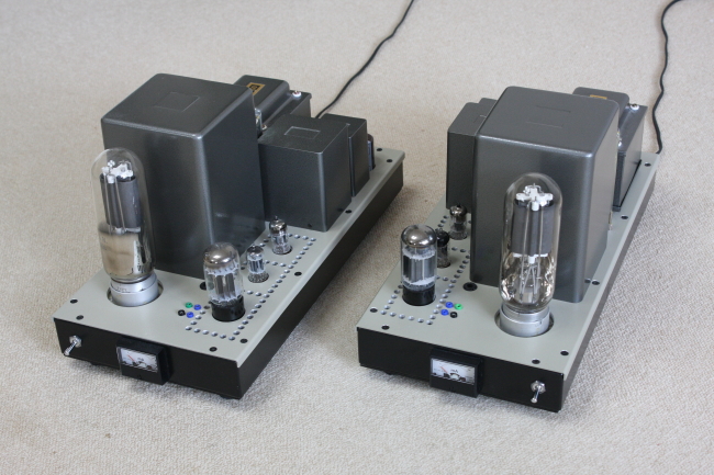
Photo of 838 SE Amp |
An 838 SE Amp (35W) with regulator tube drive (CF + CCS)
|
|
|
Photo of 838 SE Amp |
1) Introduction
The 838 SE Amp is the latest and the fourth Amplifier assembled employing regulator tube drive method built in
year 2006. I have acquired two pair of Sockets (fine craftsmanship) mated for 838 with a mark of GE via Internet
auction. It is assumed to be OEM production by James Millen, and that it was a triggering of this project as I
have had two pair of GE 838 in my stock for 10 years. With regret, the socket is becoming difficult now to obtain
rather than the tubes themselves. So far I have assembled a pair of 811A SE Amp in year 2000, then two pair of
100TH SE Amps built; One for my friend and another for my own use based on the same drive method.
2) GE-838
GE-838 is a high-mu triode transmitting tube designed for zero bias PP modulator. The plate dissipation is 100W,
and Filament voltage 10V (3.5A) and its appearance is the same as 211 or 845. Nowadays, it is getting difficult
to find NOS 211 or 845, but 838 is relatively easy to get at reasonable price. Amplification factor of 838 is approx.50
according to the AMPEREX data sheet.
Working conditions:
The 838 SE Amp runs on A2 class with plate voltage of 673V, 110mA (no signal), with +26.6V grid bias applied and
120 mA (max. grid exciting signal of 74.5Vrms ) to achieve 35W output. (THD of 3.9%)
The grid current at maximum output is 21.5mA and its resting grid current is 11mA. Plate loss of 838 at no signal
is of 74W, and at maximum output is 46W (81-35=46), which is ample room to the specified Max. plate dissipation.
(100W)
5998A: Plate current of cathode follower unit is 52mA (no signal) ~ 63mA (at maximum output) and its current of
constant current source unit is 41mA. To attain 110mA of plate current for 838, the grid bias of 5998A is adjusted,
resulting to minus 9V.
3) Custom-designed output transformer, power transformer and choke
As there are no such a big SE output transformers available in the general catalog, we have to order ISO Co.
(a succeeding Company of TANGO) to fabricate output transformers under custom-designed number S-2363 of following
specifications;
When cathode NFB is functioned, actual load impedance of the output transformer shall increase to 4.8K ohm and
feedback amount is 6.2dB.
A snap switch is provided which can select O/A NFB or Local NFB. When local NFB (4.5dB) is selected, the dumping
factor is 1.6 and when O/A NFB (6.5dB) is selected, the dumping factor increased to 4.0.
The power transformer under custom-designed number S-2417 also ordered to ISO Co as well. In addition, the
double wound choke S-2365 also ordered to ISO Co. These output transformer and power transformer were so designed
that can apply to 100TH SE Amp as well.
4) Chassis structure and layout
All amplifiers are monobloc construction. The chassis of the 1 - 4th amplifier are all SL-15 of ex Suzurando.
( SIze: 460mm in length, 220mm in width, and50mm in height )
It was designed to arrange the output tube and plate ammeter in the front in all amplifiers for seeing them from
the listening position, and has laid out all amplifiers R-block and L-block to the symmetry.
As to the rear side, it is figured out to provide the input RCA jack, Canon style 3 pin chassis plug, output binding
posts, AC inlet cord and Fuse holder, etc.
To secure the chassis stiffness, 3mm thick aluminum plate was attached to the top plate (underneath), resulting
top plate of each amplifier has 5mm in thickness. Additionally, 1.2mm thick bottom steel plate was replaced
with 3mm thick aluminum plate, so that the bottom plate could install the cooling fan. (DC12V, 60mm in diameter)
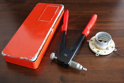
3mm screws were replaced with 4mm screws for fixing plates and the chassis frame (made of aluminum of 2mm thickness
welding structure). Name (not identifiable) of the tool (made in UK), for integrating 4mm nuts onto the chassis
frame by pressure, which is a quite useful tool for me.(see photo)
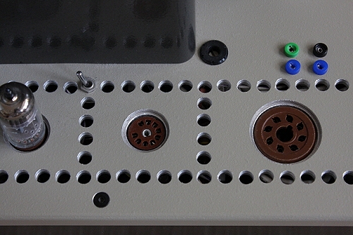
MT and GT sockets should be used a type of " bottom attached " one and holes of a chassis top plate and
lower plate are 23mm/20mm and 35mm/30mm with the same wick respectively, otherwise pins of the tubes can not insert
sufficiently into the sockets. By using two layers top plate,it is beautifully finished up without appearing all
the screw heads for fixing small parts such as the sockets, terminal strips, etc.
The chassis improved its strength, and that it can endure to the weight of 24Kg without troubles by above modiffications
done.
It is also a significant merit in view of heat dissipation by using all aluminum chassis together with cooling
fan.
|
|
|
|
Top view of Sockets |
Tool & Socket |
5) Others
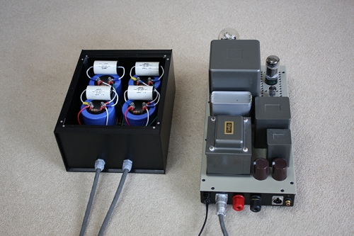
Experiment was attempted to add four 4,700 micro farads (400V) electrolytic capacitors, to those of 838 or 100TH Amps by cable tentative connections. It seems and confirmed good (favorable) effectiveness for the sound. In the meantime, one of 838, its filament has disconnected after 10 days of operation (due to assumingly cold emission). On top of the result, an external condenser box (140 x 330 x 260mm) was fabricated containing four 4,750 micro farads electrolytic capacitors ( actually working 2,350 micro farads, 800V per channel) for connecting and disconnecting with those of Amps by means of Plugs and Sockets for enjoying sound difference. As a counter measure; discharging remaining electricity quickly, a shorting circuit is prepared by 2K ohm (10W) resistance in-between high voltage line and grand as soon as main power switch is cut out.
|
|
|
|
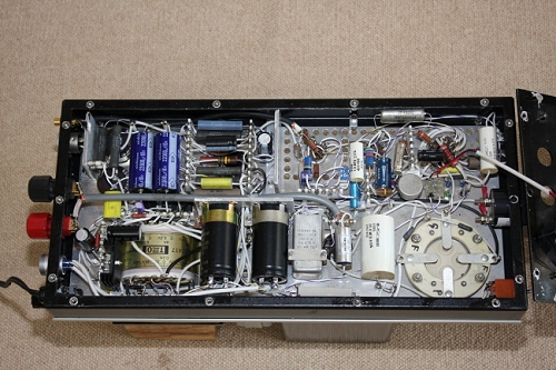
View under chassis |
External capacitor bank |