 |
|
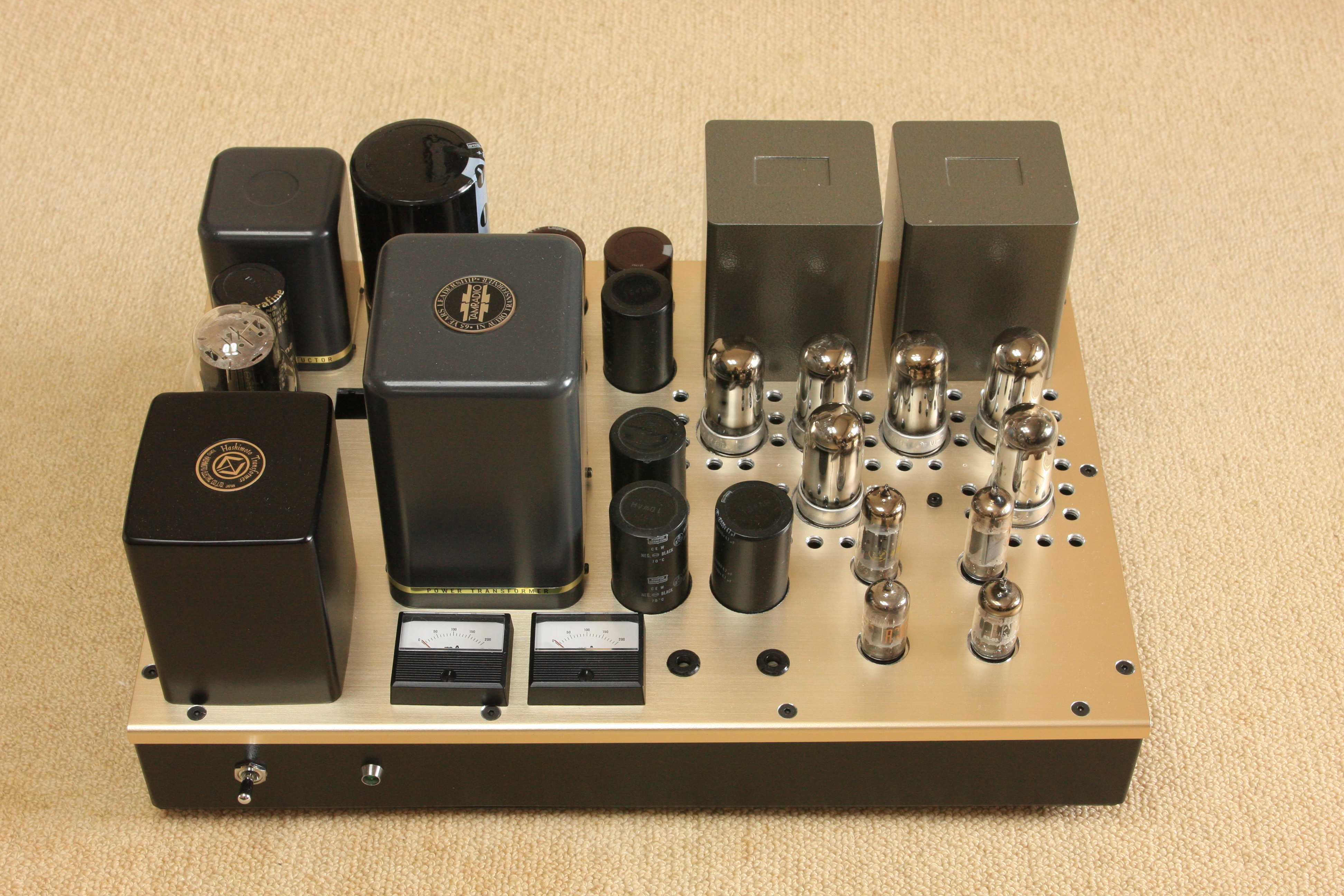
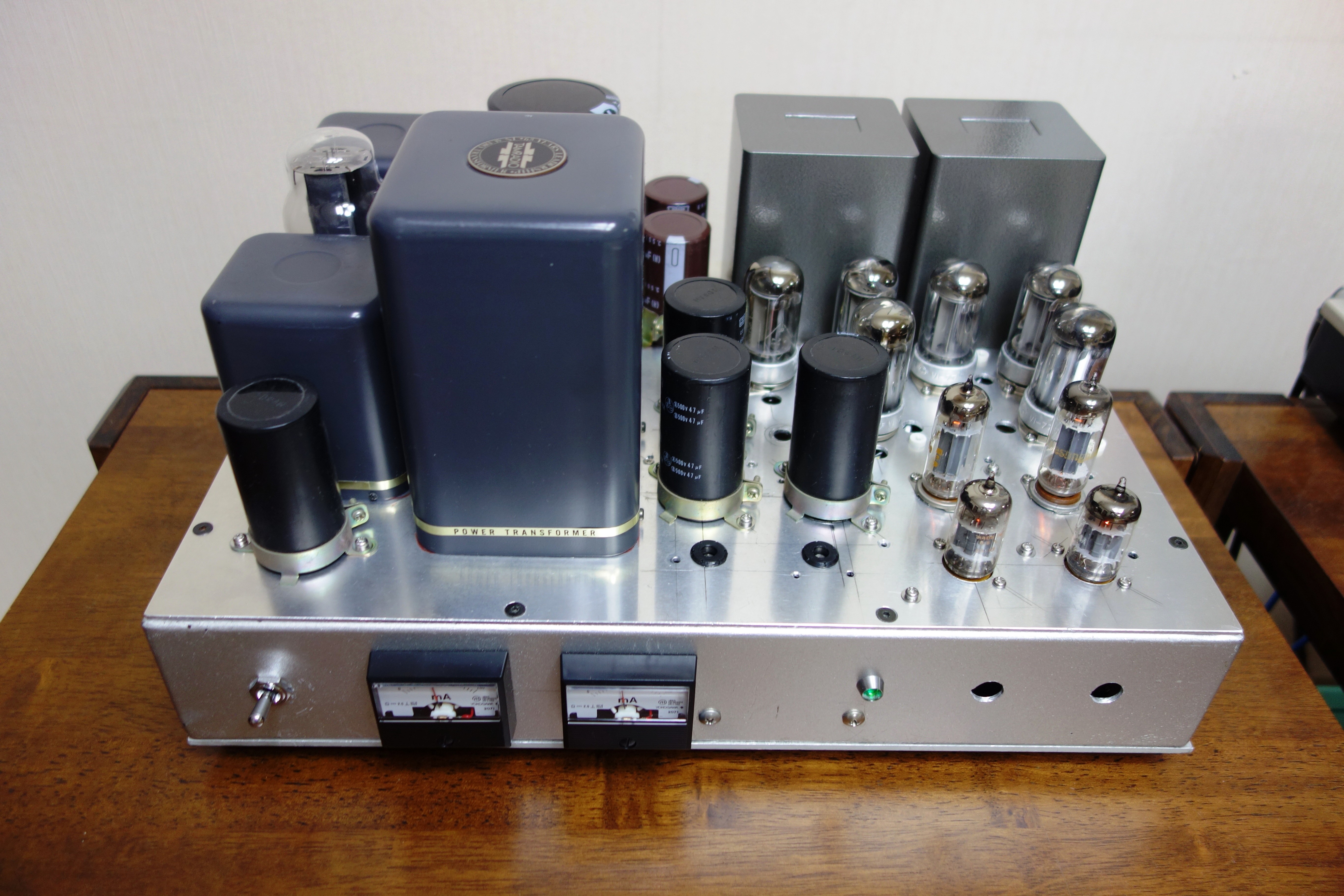
Photo of 4P1Lx3 PSE stereo amp |
4P1Lx3 PSE Stereo amp (8W)
Motivation of building 4P1Lx3 PSE and its design concept
As I have kept a ISO-Tango OPT XE-20S on the shelf for years as ISO-Tango unfortunately announced to close, so I made an farewell order of that OPT in 2013 without definite plan, and to utilize some 4P1L tubes as backup in hand as I once built an 811A SE amp with 4P1L choke loaded cathode follower drive in 2013 with which I am still enjoying to its lovely sound immensely. Fortunately, I have a Tamura power- trans-former (PC-3004) in my stock as well.
So I decided to assemble a low heat emitting amplifier employing the above components namely for summer use. Meanwhile my other transmitting tube amps are good as for heating devices in winter, but not for summer at all.
The basic idea was of an inspiration from the article by Hajime Tatsuguchi (Japanese) of PX-4 SE Amps appeared on the Radio Gijyutsu Magazine published in February and March 2004. What he claimed was that the sound of old DHT power tube having good linearity is the best and that there is no choice for alternatives. So he attempted to build a power amp using PX-4 idea in lowering a factor of disturbing sound quality as much as possible.
|
|
Photo of 4P1Lx3 PSE stereo amp |
The core of the amp is to challenge for high-fidelity needless to mention and that an output signal wave form should be identical to the input signal wave form at the output point. It is generally said to be enough that basic characteristics are met with those criteria a) Frequency response, b) THD and c) Signal to noise ratio. However it is also a fact to note that sound quality may be influenced by amplifiers, although it is for sure that today`s Hi-fi amplifies have reached to the level of good enough. Additionally, Hajime Tatsuguchi commented that stability of the amplitude is one of the key factors: a function of the amplifier is amplification and the Hi-fi amp must fulfill preconditions of constant and stable amplification without any fluctuations by the external disturbances. Three basic characteristics are to have a real meaning provided the said conditions are met. In case of this amplitude be fluctuated by external disturbances, the output signal would be distorted accordingly in relation to time elapse. As voice or music is always fluctuating as time elapse, so its wave forms alter in relation to time elapse, thus it is crucial in characterizing overall sound quality.
In case of amplitude level is altered, this would be transferred the original to the output and that it would be influenced to the total sound quality especially in the areas of separation and resolution of the sound, which are deeply co-related to the stability of amplitude of power amplifier. The alteration of the signal, namely the envelope of the voice or music is to be detected by the non-linearity of the output tube at the plate circuit, and therefore a plate current fluctuates in response to the envelope of the signal. I assume there are effective measures to improve the stability of the amplitude of the power amplifier.
 |
 |
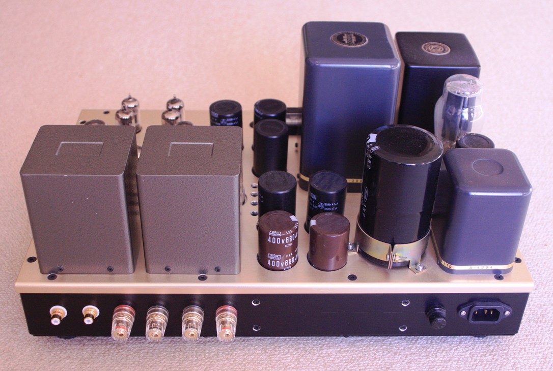
Rear view |
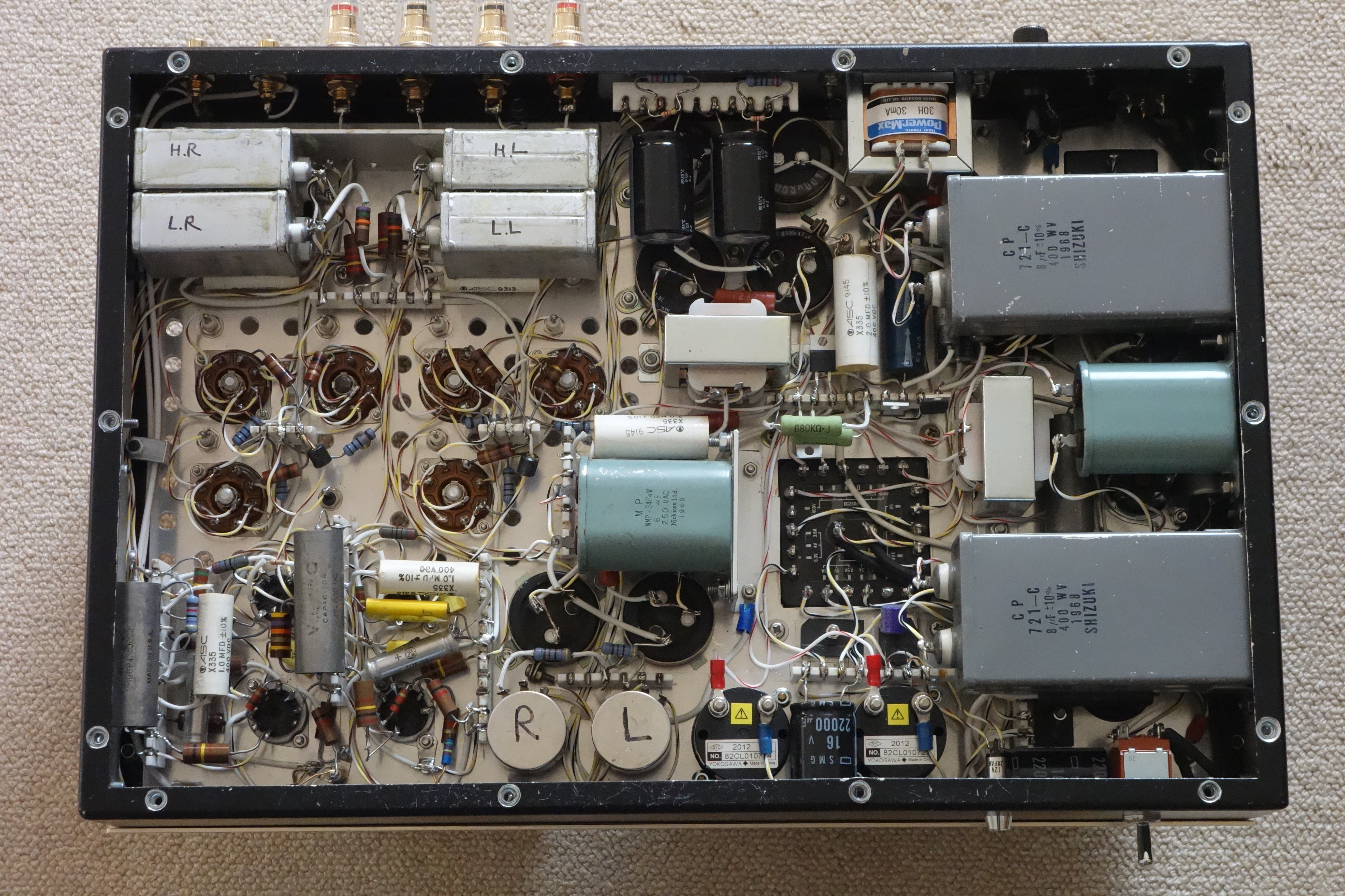
Bottom view |
Å@Å@Å@
a) Use an excellent power-tube 4P1L known better at linearity in triode connection with no NFB SE amp.
b) L-C-L-C filter PSU is the best for enhancing sound quality.
c) Increase time constant at the decoupling circuit in the output stage (2,200mF).
d) Add Oil paper or MP condensers to the electrolytic condenser is a viable solution for enhancing sound quality as for absorbing high order harmonics.
e) Independent PSUs each for the power output stage, voltage amplifier, and CF driver with CCS.
f) Heater or filament circuit must be supplied by DC (except rectifier, 5R4) for ultimate ripple removal.
As a consequence, the residual noise of the 4P1Lx3 stereo amp lowered to 0.07mV/ (A) for no NFB amp.
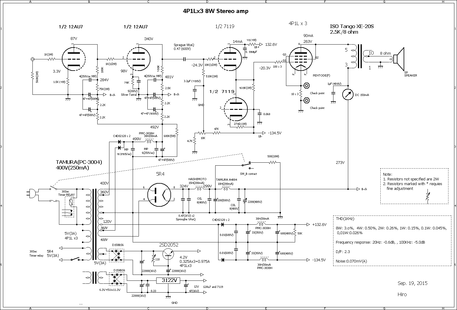
Schematic of 4P1Lx3 PSE Stereo amp
The circuit descriptions
1) This 4P1Lx3 PSE amp runs on class A2 at 265V / 90mA to achieve 8W output.
2) The HT for 4P1Ls, using a choke input circuit with full-wave rectifier by 5R4 from 400V tap to get 275V/200mA. The first choke is designed for the choke input use, Hashimoto C-15-200CH.
3) A 30 Sec delay timer installed in the filament circuit of the 5R4, for avoiding to the violent fluctuation response for the 4P1Ls in start- up period.
4) Due to a big amount of decupling Cap.(2,200mF) used in HT circuit, cold emission of 4P1Ls is concerned, so a 500 ohm resistance prepared to earthed from HT at the same time when power switch is cut off.
5) The HT for the voltage amplifier using a small (6mF) capacitor input circuit with a 30H/30mA choke with full-wave rectifier by Silicon Carbide Schottky Diode from 360V tap to get 500V dc.
6) +- PSU for the Cathode follower driver and CCS stage is to using half wave rectifier by Silicon Carbide Schottky Diode from 120V tap with a 30H/30mA choke respectably. This stage needs sufficient current for A2 operation of the 4P1Ls.
7) Ripple suppresser circuit with transistor is provided for the filament PSU (4.2V/0.325Ax3=0.975A) for the4P1Ls.
8) The test pin jacks are provided on the top plate of the chassis for measuring of each 4P1L`s cathode current.
Measurements
 |
 |
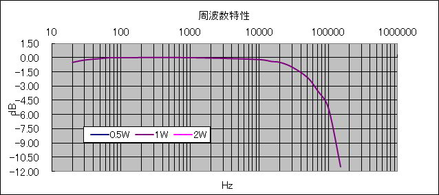
Frequency Response Graph |
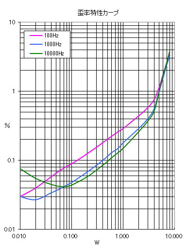
Total Harmonic Distortion Graph |
 |
 |
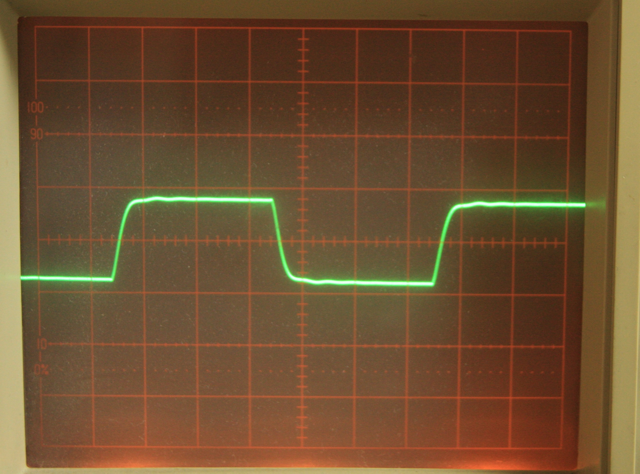 |
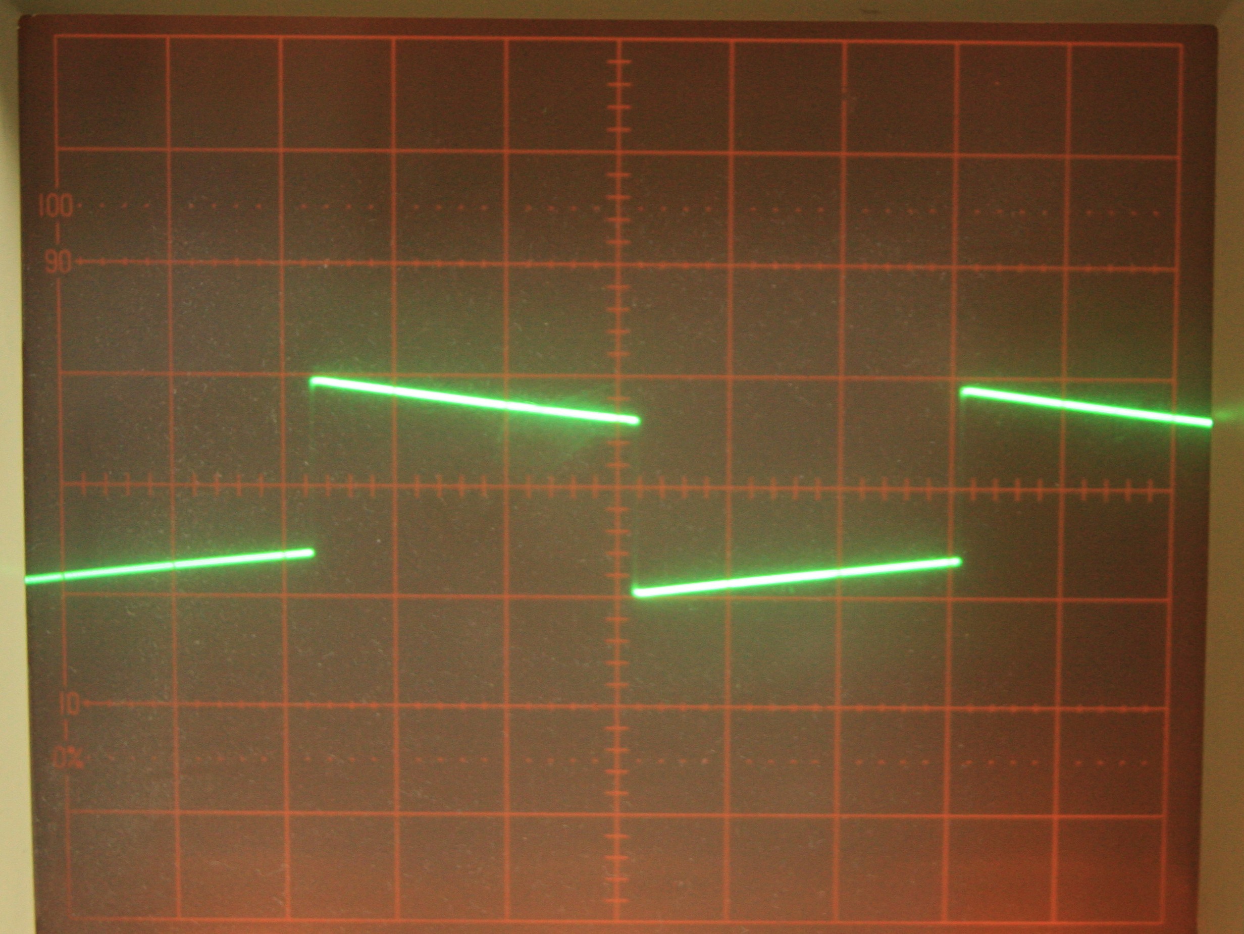 |
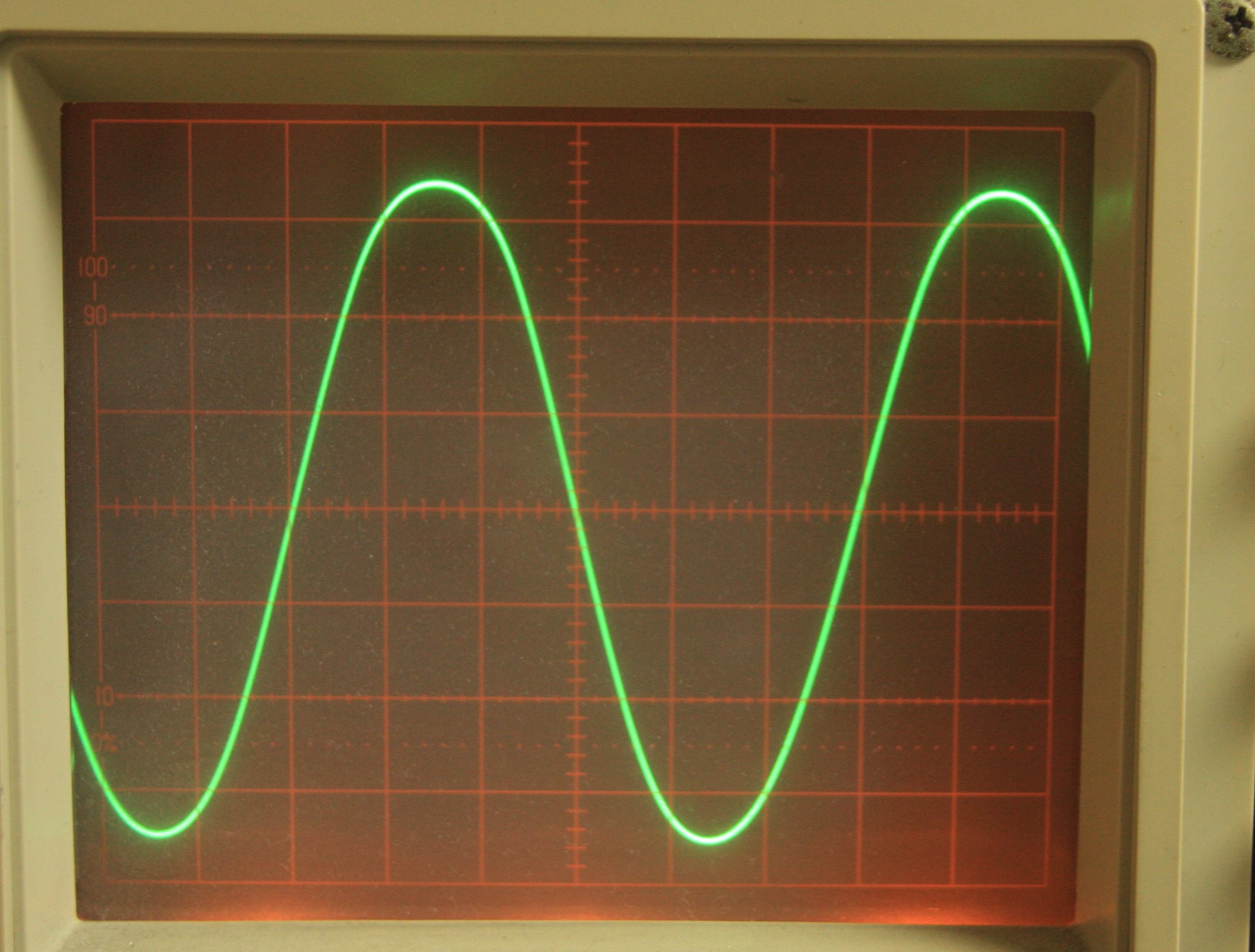
(8W-1KHz) |
(1W-1kHz) |
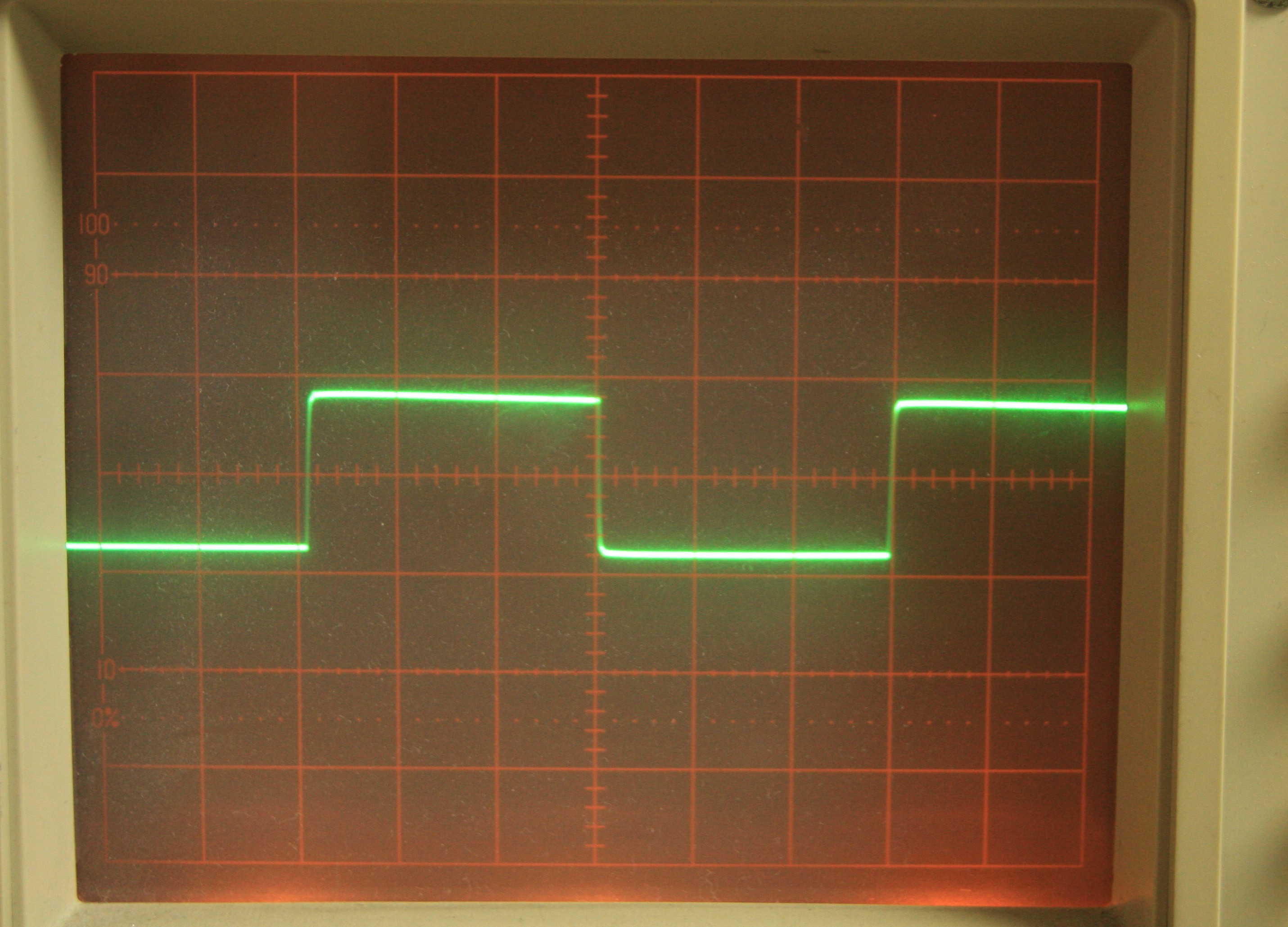
(1W-10kHz) |
(1W-100Hz) |
Å@Å@Å@
Dumping Factor (On/Off method at 1KHz, 1.25W): 2.44
Residual noise: 0.07mV (A)
Summary of this project
This 4P1L project was initiated in March 2013 and terminated on September 2015 fulfilling key objectives.
At first, I tried an idea of grid leak resister 200K ohm for fixed bias like a standard approach, and its output power was only 4.5W due to the fact of the grid current of 4P1Ls starts flowing out (its bias voltage went to deeper).
So, I made another try to replace the grid leak resister with a grid choke and battery bias (14 unit of size AA battery in series for -21V).
The output power jumped up to 7W, and that its sound has become further up graded. Then I attempted to replace the battery biasing with a 7119 as a direct coupling cathode follower with CCS on my experimental 4P1Lx3 PSE amp and the plate voltage on the 4P1L raised to ca 280V in A2 class.
As a result, the output power became increased to 10W with non clipping and THD was improved in all output ranges.
 |
 |
Experimental 4P1L PSE amp |
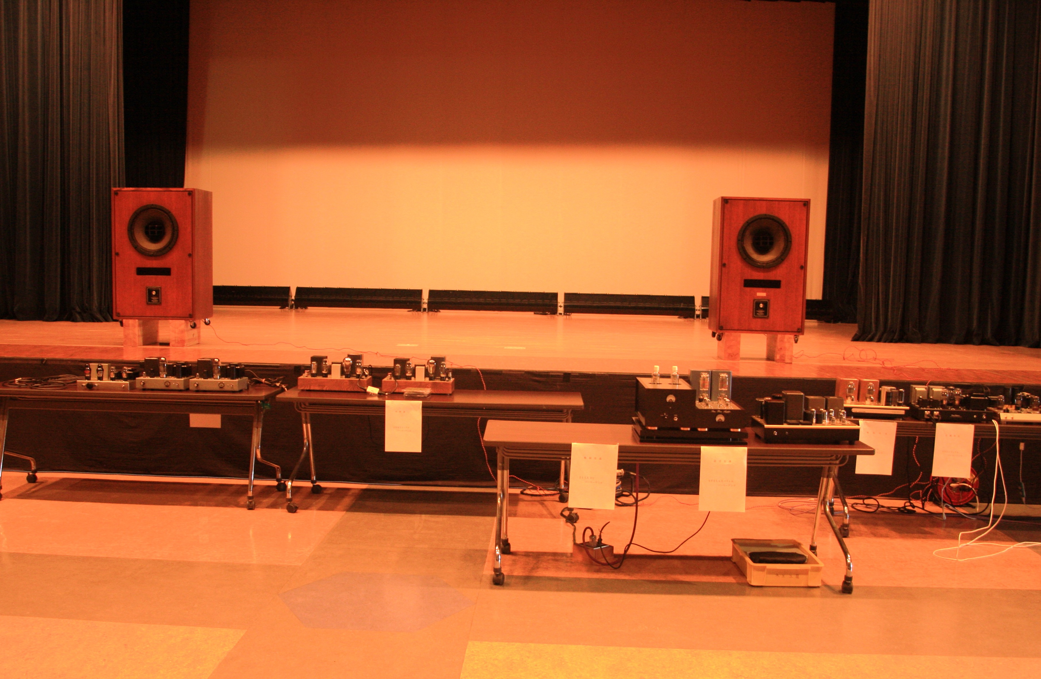
Toyama exhibition |
Taking an opportunity to participate to the 28th Toyama craft audio club exhibition held on October 3, 2015, I re-built a 4P1Lx3Å@PSE(8W) amp from scratch on a new chassis, TAKACHI SRDSL-20 (W450 x H68.2 x D305mm) in August and September 2015.
Feedback from the audience to the 4P1Lx3 PSE amp was favorable one as follows:
- The sound was extremely visible one in front stage, had a superb resolution sustaining high dynamic range.
- Today`s best sound, especially good balancing in high region and low end energy for the SE amp.
- Wonderful in low and mid range, but highs was a little rough.
In the meantime I have made a few fine adjustments and I have been enjoying this amp for years with full of satisfaction namely in listening CD as BGM.