Third version of the 811A amp
(4P1L choke- loaded cathode follower drive)
A new idea raised
It may be feasible that 4P1L can be used as a cathode follower driver to the 811A SE amp unlike an idea of 5998A
possessing inherent cons such as a) minus voltage PSU needed, b) too much head room for driving to the sensitive
tube of 811A. Early this year (2013), I decided to re-build the third version of 811A SE amp (trial) employing
a 4P1L choke-loaded cathode follower (capable to drive even to minus region without minus power supply) replacing
the regulator tube driving method (CF+CCS) used for more than a decade.
After a month of trial and error phase, I succeeded in getting full drive to the 811A SE amp (20W) with the 4P1L,
and its sound was gently warm and mild. As a result, I can enjoy listening to any kinds of music under peace and
relaxing due to seemingly its low distortion (THD) behaviors.
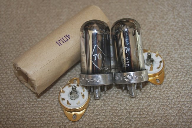
The 4P1L is an inexpensive small Russian made DH pentode for military use, yet well- built.
I guess its max plate dissipation in triode connection should be around 8W.
I became interested 4P1L tube having a center tap of the filament, which is fitted to the cathode follower circuitry
as output.
6AS7 series regulator
Incorporated two of ügseries regulatorsüh, one for output power stage (600V) and the other for voltage amplifier
stage (500V) by employing a 6AS7 (twin triode) which was initially adopted in my801A x 3 PSE amp build in 2011
and so far which is working well..
( please refer to my HP of upgrading 801Ax3 PSE amp)
Overall performances of the third version of 811A SE amp
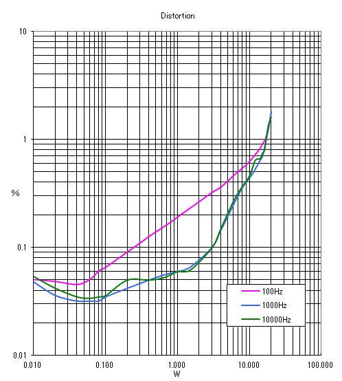
In general, the third version of 811A SE amp came out with greater success than I anticipated at sound quality
as well as their figures measured.
The distortion(THD) level is considerably lower thanks to 8.2dB of cathode NFB, 5.2dB of the local NFB and only
1.0dB of global feedback; 20W:2.0%, 10W:0.46%, 1W:0.024%, 0.1W: 0.018%.
D/F: 2.3. Residual noise: 0.14 mV (A). Frequency response; 20Hz: -0.55dB,
100 KHz: -2.2dB
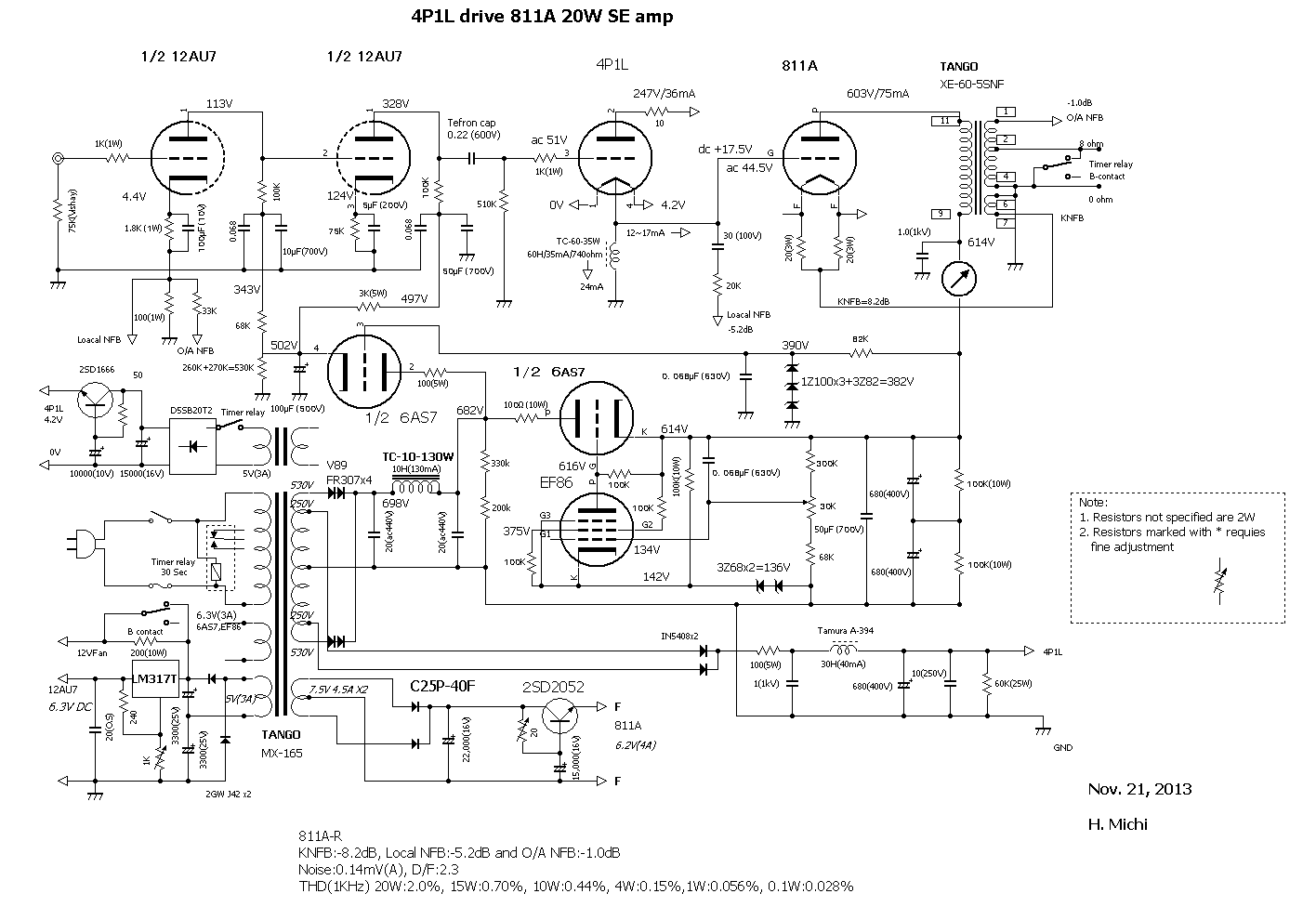
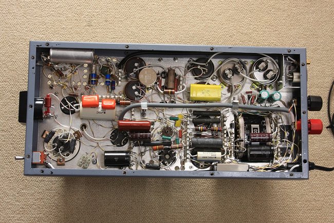
The Circuit descriptions
The cathode choke for the 4P1L is of TC60-35W (60H/35mA, DCR: 730 ohm) ex-Tango which was originally designed for
the plate choke use (for the small power tube use).
The grid current for the 811A is 12mA in resting condition, so that actual current through the choke is 36-12=24mA.
Consequently, the grid bias for the 811A is: V=0.024 x 730=+17.5V
To obtain the above conditions, precise adjustment of 4P1L plate voltage is of essential ( 100 ohm in series resister
and 1 ā╩F(1KV) at input of 30H/40mA choke).
The operating points of the 811A:
Plate voltage: 600V, Grid bias: +17.5V, Plate current: 75~80mA, Max. exciting voltage: 45Vrms at 20W output, Load
impedance of OPT: 5.9K ohm.
OPT is XE60-5SNF ex-Tango: 30W (40Hz), primary impedance is 5K ohm with 36 ohm 3rd winding and the cathode NFB
is 8.2dB.
The 30 sec. delay timer installed in the filament circuit of the 4P1L for avoiding rush current for 811A during
start-up phase. Note: I have learned that 6AS7 was making sparking in case no delay timer installed.
The purpose of HT series regulators is to secure a) lower impedance, b) to obtain sufficient separation between
output stage and voltage amp stages, and c) capability for gradual start up for avoiding extra high voltage (friendly
to capacitors).
Three negative feedbacks are used in the circuit, the KNFB, local NFB and global NFB. Local NFB and global NFB
are returned to the same point, the cathode of the first stage of the voltage amplifier.
Adding a small amount of global feedback (1.0dB) is a kind of secret sauce to quiet the sounding.
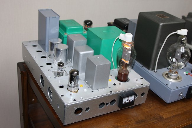
Construction
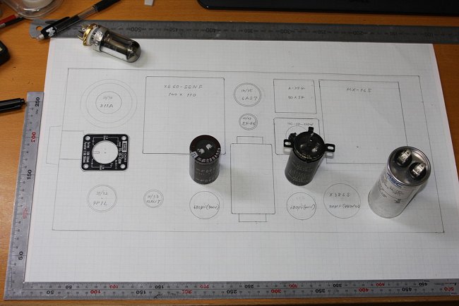
Chassis layout:
As having neither the CAD nor a drawing board with me, I made a layout drawing with a steel square, rules and a
caliper on the graph paper at an exact size.
With recent copy machine, it is possible to make mirror copy from original drawing. So the complete symmetric L./R
layout drawings are to be made instantly. Adhere them onto the top plates or its underneath plates of L&R chassis
for manual machining.
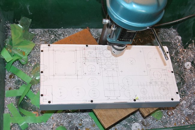
Metal work:
The chassis of all my amplifiers are consolidated to SL-15 of ex- Suzurando.
(Size; 460 mm in length,220mm in width and 50mm in depth)
Reasons are due to limitation of depth of the throat of my boor-bank drilling machine, and it is re-usable the
chassis frame and bottom plate. So only two plates (3mm thickness aluminum sheet) for the top and underneath to
be attached to top plate are required.
As a result top plate of each amplifiers have become to 6 mm thickness in total. To keep it perpendicular, boor-bank
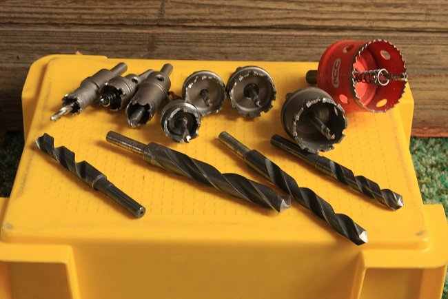
drilling machine and hole saws are absolutely a must
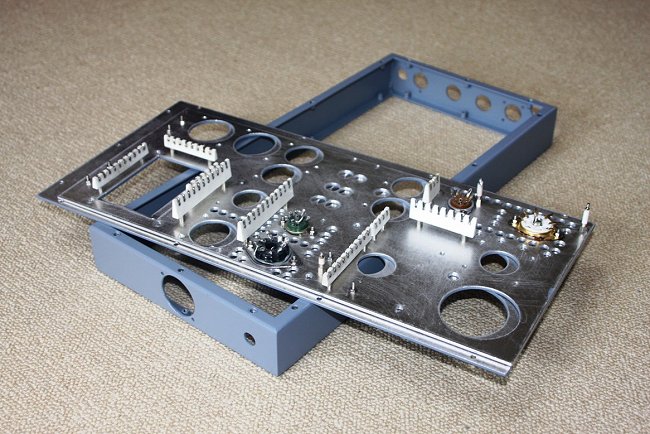
Use coaxial cable (RG58/5D2V) for wiring between secondary taps of OPT and output binding posts as the speaker
cable draws big amount of current at where better magnetic shield is mandatory in the chassis.