 |
|
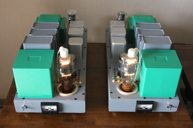
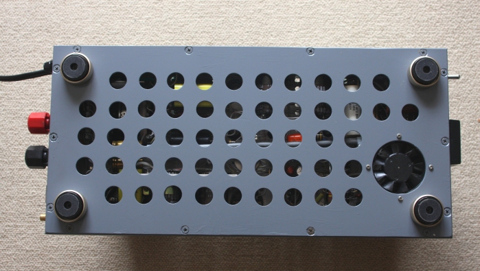
Photo of renewal 811A SE Amp |
Renewal of 811A SE amp
So far, I received several inquiries via e-mail about my 811A SE amp from different continents. Taking this opportunity,
I wish to introduce the upgraded one since the new 811A SEÅ@amp is renovated substantially from the one on my internet
home page.
|
|
Photo of renewal 811A SE Amp |
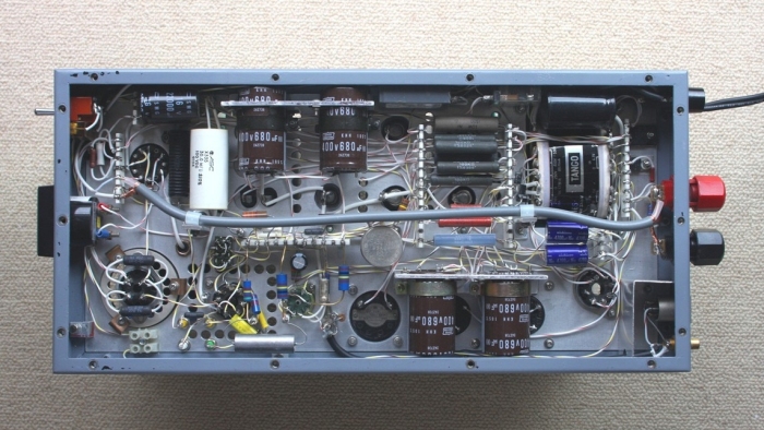
I built an original 22W 811A SE amp in 2000 adopting so called regulator tube drive method for the first time. In the meantime minor modifications were attempted accordingly. In 2009, I have built a new 811A SE amp from scratch basis utilizing knowledge learned from the regulator tube drive 838 SE amp (35W) build in 2006. Highlight of 838 SE amp was of providing additional capacitor bank externally deriving from massive electrolytic capacitors Åi2,350 micro F / 800VÅjand oil-paper condensers (8 micro F / 1Kv) combination aiming at immense enhancement of decoupling and reduction of ripples in the power supply. It was designed to provide such a capacitor bank away from the chassis (ex-SuzurandoÅfs SL-15,Å@460mm x 250mm x 50mm) due to no space available. Capacitor behind the rectifier of the high voltage power supply is of oil paper condenser (8 micro F / 1KV). Decoupling capacitor of the first voltage amplifier is of oil paper condenser(4 micro F /400V) with which a smooth and clear sound have been obtained.Å@
Å@Å@Å@
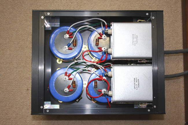
A new 20W 811A SE ampÅiregulator tube drive method) was designed and built on the SL-15 chassis (frame re-used
only). Compared to the 838 amplifier, all components were accommodated on to the same chassis, as power transformer
(ex-TangoMX-165) and output transformer (ex-Tango XE-60-5SNF) are smaller. Three oil paper condensers(10 micro
F / 600V) and an oil film capacitor (10+50+50 micro F / 700V) made by Touitu Denki were successfully mounted in
the same chassis as well. I made re-painting to those output transformers and the power transformers in emerald
green for good appearance due to nearly 20 years usage. Difference between old and new circuit diagrams are: filter
and decoupling circuits are truly reinforced. Capacitors in the decoupling circuit for the output tube have increased
to 350 micro F from 100 micro F (1,000 micro F preferable), and a choke coil of 30H (40mA) was newly installed
for voltage amplifier.
In theÅ@low voltage B + - power supply, capacity of the electrolytic condenser in the choke input circuit was enhanced,
and added film capacitors in parallel connection. For the relative load impedance to increase, it was reduced its
plate voltage to 811A as well as its plate current increasing. As a consequence, it was perceived improvement of
smoothness and grace in sound by those modifications, though its maximum output fell down to 20W from 22W.
Reasons why I decided to build these 838 or 811A based amp were due to a hint of the theory claimed by Hajime
Tatsuguchi: articles describing of PX-4, VT-52 and 801A SE amps on the Radio Gijyutsu Magazine issued in 2004.
What his idea is to be attributed to a word Åhstability of amplitudeÅh which is absolutely a base for defining
basic elements of amplifier: a) frequency response, b) THD and c) signal to noise ratio. As amplifier varies its
amplitude by the external disturbances from time to time, and which causes output signal would be distorted in
relation to time elapse.
As signal of voice or music is always fluctuating as time elapse, so its wave form changes in relation to time
elapse would be an important element of characterizing sound accordingly. In case amplitude level is altered, this
would transform the output signal and it will influence sound quality. Especially separation and resolution of
sound are deeply related to the stability of amplitude of power amplifier.
|
|
|
Below are the major points influencing the amplitude of power amplifier.
1) Power tube of poor-linearity: with the poor-linearity of output tube, the envelope of sound or music signal
is detected, and which appears at the plate circuit, and influence plate current fluctuation in response to the
envelope.
2) Poor-linearity of voltage amplifier tube: variation of the final B voltage influences to the plate supply voltage
of the preceding amplifier. In case of a voltage amplifier tube is inferior in linearity, amplitude of this amplifier
would be inevitably fluctuated. In general decoupling circuitry, it is often observed not enough to attenuate at
extremer-low-frequency range.
3) Ripples of all power supply: could slightly affect "amplitude stability"of amplifier by the remaining
ripple of A, B and C power supply voltage.
4) Counter-electromotive force generated at speaker: this counter-electromotive voltage would lead plate voltage
change of the output tube, and that its amplitude stability would eventually be affected resulting the incoming
signal be modulated, particularly in the inferior linearity output circuit.
Consideration to lower these causes of influencing of amplitude of power amplifier:
Use good linearity power and voltage amplifier tubes: as good linearity tubes are smaller in fluctuating amplitude
against variation of plate supply voltage. It is advised to apply + bias in case zero-bias DHT transmitting tubes
used, and to be set flowing its grid current constantly in A2 operation with better circuitry in linearity, particularly
using an output transformer which has KNFB winding, the characteristics of zero-bias DHT tubes (high mu) would
turn quickly to low ÅimuÅj tubes such as 211 or 845 which are often said to be nice sounding. Regulator tube drive
method is unique in splitting power supply for the drive stage and output stage which is also effective to the
sound quality.
Increase time constant of a decupling circuit of voltage amplifier and output circuit. The output side of power
supply capacitor has a role of the decupling of power supply and an output circuit, and simultaneously with the
role of ripple removal.
Verified that oil condenser to add to electrolytic condenser is a useful solution to enhance sound quality as an
energy absorber in high older harmonics.
Near future: for lowering impedances at power supply output, a semiconductor AVR is to be built in replacing 250
ohms (20W) resisters connected between rectifier tube output and pi-network filter.