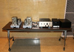
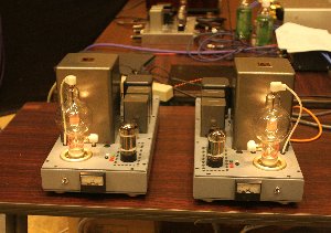
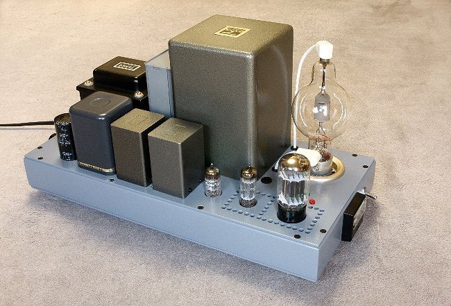
Renewed 100TH SE amp
Renewal of 100TH SE amp (27W) with regulator tube drive (CF+CCS)
Renewed 100TH SE amp
1) Purpose
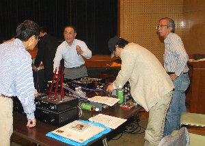
Taking an opportunity to participate to the 18th Toyama craft audio club exhibition held in Toyama-city on October
9th. I reviewed the 100TH SE amp based on the regulator tube drive and re-designed for exploring well balanced
sound which I have learned a solution through renewal of 811A SE amp in year 2009. Please refer to "Renewal
of 811A SE amp" on my home page.
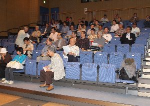
There were about 80 people gathered and exhibited 8 different kinds of amps. Every exhibitor was given 30 minutes
presentation for playing LP records or CDs including one common music. The loud speaker was Altec 620A. This exhibition
was not intended to determine ranking whose amp is the best rather to hear direct comments from the audience later.
Mr.Minakami reporter to MJ magazine made a summary of reputation gathered from the audience:
a) sound was of wide range, though it was soft and smooth,
b) there was no disturbing sound,
c) good stage and depth especially at vocal,
d) sound of string instruments was of crisp and further extension in high region. It was elaborated in the convention that this amp was one of the best amps in the exhibition.
|
|
|
|
|
2) History
My first 100TH SE amp was built in 1995 adopting the dynamic coupling method, driven by 5881 and its out put was
23W. Then, I tried to build another 100TH SE amp using Sisido method, and its out put was 22W. On that amp, I employed
a combination of an inter-stage transformer #10672 and an output transformer #10887 of which Mr.Sisido ordered
to ex-Tango especially for his 805 SE amp.
In year 2000, I contrived a transformer-less method (Inversed inter-stage transformer) and applied it to 811A SE
amp and its output was 22W, I named it later "regulator tube drive".
In year 2003, I built again100TH SE amp from scratch base adopting the said regulator tube drive method and succeeded
in pulling out to 30W. Up until that time, I was regretfully attempting to increase output power rather than total
balance of sounding etc.
|
|
|
|
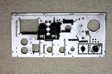
Bottom view chassis top plate(3mm+3mm) AL sheet |
Bottom view |
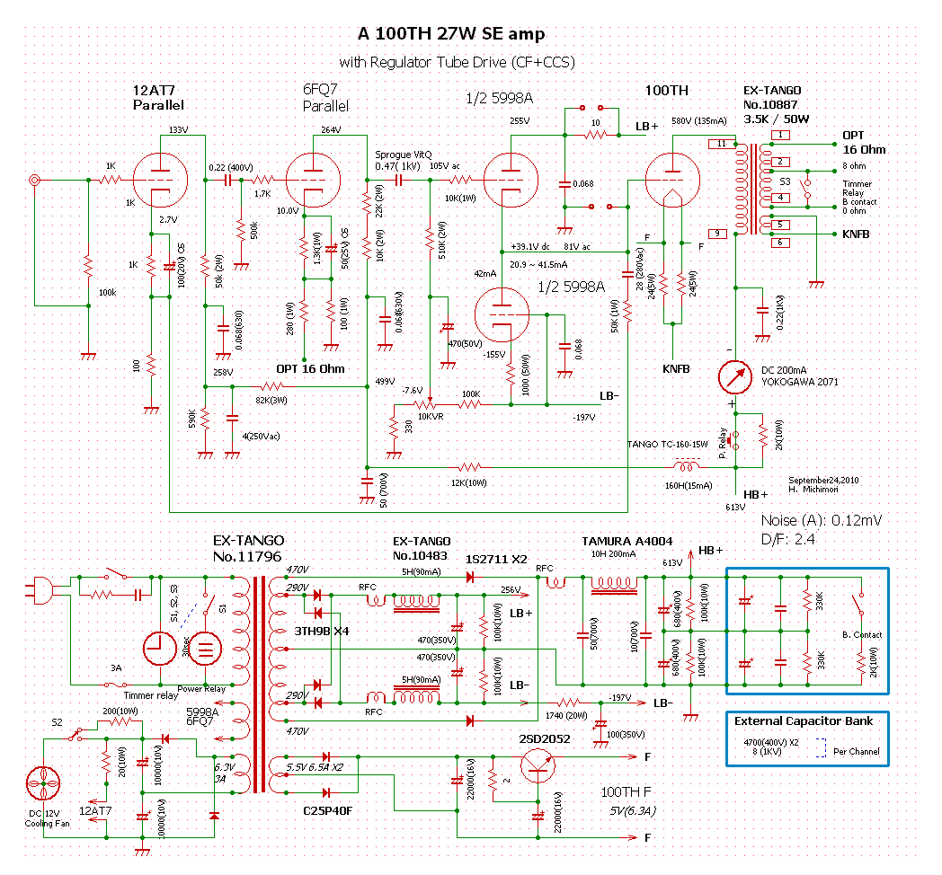
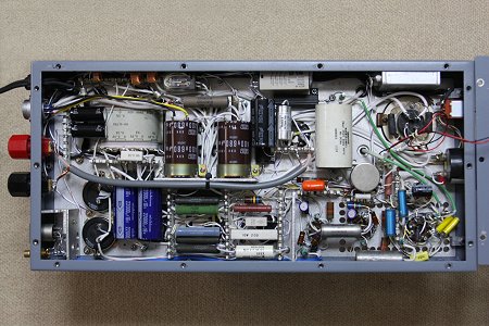
3) Highlights of the renewal
1. Changed parallel connection of 5998A (cathode follower) to one unit of 5998A. The current to cathode follower
of 1/2 5998A is in the range from 60mA (at idle) to 80mA (at maximum output). 260 - 40 = 220V, 220 x 0.08 = 17.6W
which is exceeded maximum plate loss of 15W. However concerning to AF output power, it is acceptable.
2. Dismantled 6C19P for CCS circuit and replaced it with another unit of 1/2 5998A similar to my other amps.
3. The current to CCS of 1/2 5998A is set 38mA.
4. Mounted a 160H / 15mA choke exclusively for reinforcement of decupling circuit in the voltage amplifier stage.
It is indeed a valuable investment to adopt expensive high inductance choke in order to obtain clear sound.
5. Installed a 4 micro F (250V AC) of MP capacitor for the decoupling of first stage of voltage amplifier, and
at where electrolytic capacitor in parallel should not be used.
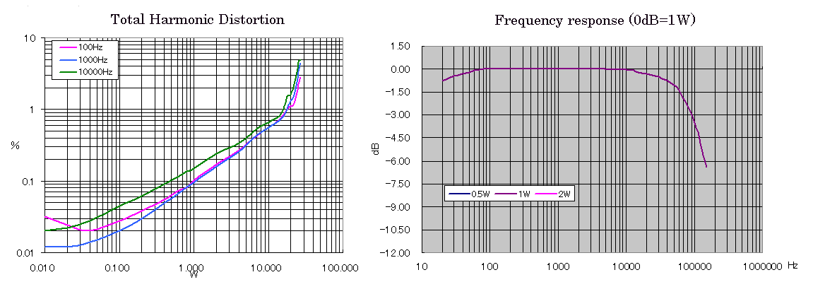
6. Set 100Th plate current to 140mA from 120mA, and plate voltage downed to 590V from 610V , as a result relative
impedance of output transformer was raised, with which it was attained a) lowered distortion and b) well balanced
sound (enhancing bass), though its maximum output downed to 27W from 30W.
4) Regulator tube drive (Cathode follower & constant current source)
1. Extremely high efficiency for A2 class operation: output power vs. input power.
2. Capability to higher grid current of power tube (20 ~ 40mA for 100TH).
3. Wide window of bias voltage setting of power tube (+40V for 100TH).
4. Higher gm tube (15,000 of 5998A) makes CF output impedance lower (1/gm = 66 ohm for 5998A)
5. Lower impedance and 100% negative feedback of CF circuit assure strong in stability against various transient
response (e.g. signal & bias voltages are not influenced when power tube grid draws higher current). (max.
82Vrms signal, +40V bias and max.40mA grid current for 100TH)
5) Circuit description and others
1. A 30 second muting circuit is provided against annoying noise: buzz occurred at start up time.
2. Make use of above timing relay: for speed down cooling fan for lowering noise.
3. Cooling fan is to just assist natural draft, though it is significant in lowering temperature of inside chassis
to dissipate heat generation from those of 100TH and 5998A.
4. Make slits (rectangular hole) in between output transformer and chokes or oil paper capacitor for adequate ventilation
of heat for chimney effect.
5. Adopt the capacitor box to be used alternatively with 838 amp or with 100TH amp (2350 micro F, 800V electrolytic
capacitor and 8 micro F, 1kV oil paper capacitor) for reinforcement of filtering and decoupling of the most important
output of PSU.
6. In my 15 years experiences, generic UX socket can be used perfectly for 100TH ( Anphenol mold type).