|
|
|
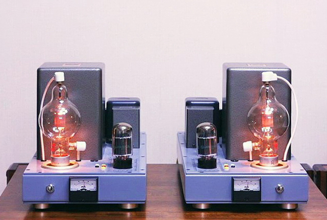
Photo of 100TH SE Amp |
100TH SE amp (30W) with regulator tube drive (CF+CCS)
|
|
|
Photo of 100TH SE Amp |
1) Introduction
First of all, I like Eimac 100TH of its unique appearance as well as reddish glow during operation.
I have made re-assembling the 100TH SE amp in 2003based on regulator tube drive method. Chronologically, I built
811A SE amp employing the regulator tube drive method and contributed of outcome to the local MJ journal (Japanease
Audio magazine) in April 2003.
On that ocaasion, I stated that next project should be a 100TH SE amp adopting the said regulator tube drive method
to certify of its driving ability to the most difficult tube for attaining listed output.
In 1995, initial 100TH SE amp was assembled adopting the direct coupling method developed by Mr. Seiya and confirmed
its output power was 23W driven by 5881, and after that, advanced to the another method of the roll over inter-stage
transformer drive, invented by Mr. Sisido in 1997 resulting only with 22Woutput.
Under such circumstances, I did challenge to achieve 30W output with the regulator tube drive method by employing
3.5K ohms output transformer #10887 and power transformer #11796 of ex-Tango once used in previous amps and its
objective was successfully accomplished.
2) Eimac 100TH (major characteristics)
- Filament (Thoriated tungsten) 5V, 6.3A
- Maximum plate dissipation: 100W
- Maximum grid dissipation: 20W
- Maximum plate volts 3000V, 225mA
- DC grid current: 60mA
- Amplification Factor: 38
- Generic UX socket and non forced air cool
|
|
|
|
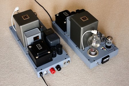
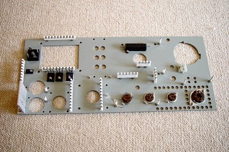
Front & rear view |
Chassis lower plate |
3) The Circuit descriptions
- This 100TH SE amp runs on A2 class at 600V / 120mA with the regulator tube drive method to achiev 30W output.
(THD of 3.6%)
- The grid bias voltage of 100TH is +39V and its grid current is varied from 21mA (at idle) to 48mA (at maximum
output)
- The plate current of 100TH (120mA) is set even at maximum output, which is different from other tubes.
- Parallel connection of 5998A is necessary for driving 100TH and its plate current is in the range from 67mA (at
idle) to 94mA (at maximum output).
- The current of 6C19P for constant current souse load is 46mA.
- The output transformer is ex-Tango #10887, rating 50W, 3.5K ohm impedance,additionally 36 ohm KNFB winding resulting
with approx. 4.2K ohm load impedance.
- KNFB is applied -5.2dB and NFB from 16 ohm of output transformer to cathod of 12BH7A is -5.5dB.
- Total NFB amount is -10.7dB (measuring value) resulting dumping factor of 2.85. (On-Off method at 1KHZ)
- The external capacitor bank (2,350 micro farads, 800V per channel) to be connected by means of plug in to the
socket.
- The reason for inverting second winding of output is set absolute phase to same as my other amps.
- Zenner Diode used in voltage amplifier means a protection over 500V at start up time period.
- A 30 second muting circuit is provided to cope with the trangents response for start up time, buzz and increasing
of plate current of 100TH occured due to violent fluctuation of cathod voltage of 5998A.
- Make use of above delay time relay, cooling fan speed is to be downed after 30 second from power turned on for
lowering noise.
- Bias adjustment for 5998A can be executed by a potentiometer from chassis top plate.
- Plate current of each 5998A units is measurable separately at the test-points on chassis top plate.
- Grid bias voltage and exciting voltage of 100TH can be measured at test-points on chassis top plate.